 |
|
||||||||||||||||||||||||||||||||||||||||||||||||||
|
|
|
||||||||||||||||||||||||||||||||||||||||||||||||||
|
Vertically Symmetric Two-Way Loudspeaker Arrays Reconsidered
The design of multi-driver loudspeaker systems is a complicated task wherein several seemingly conflicting goals must be satisfied. For example, it is felt that for optimum performance, a loudspeaker system, in addition to delivering a flat on-axis magnitude response, should be free of lobing errors and polar axis tilt [1], [2]. Unfortunately, there are only a handful of conventional two-way crossover designs which meet these requirements [1], [2]. A means of solving this problem was presented by D'Appolito [3] wherein a unique geometry was analyzed which eliminates lobing error and polar axis tilt independent of interdriver phase differences. In the last several years, the vertically symmetric two-way loudspeaker arrangement analyzed in that paper (a.k.a. the "D'Appolito configuration" or, as we shall refer to it, the "(3,2) configuration") has become widely accepted as a means of implementing superior loudspeaker designs. Having auditioned a variety of (3,2) systems in a number of different contexts, the author has noted that many (3,2) systems exhibit a characteristic coloration through the midrange that is not suggested by on-axis or approximately on-axis frequency response measurements. This suggests a significant irregularity in the reverberant response of these systems, and the hands-cupped-over-the-mouth-like tonality suggests that it occurs in the region of 1 kHz. This has prompted the author to enquire as to whether there might be mechanisms inherent in the (3,2) arrangement capable of introducing significant off-axis frequency response irregularities that have not been covered by existing analyses. In this paper, one such mechanism is revealed and computer simulations of the off-axis behavior of several idealized (3,2) systems are presented.
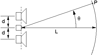
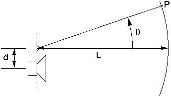
Before commencing our examination of (3,2) systems, we will first define and briefly discuss some terms that figure prominently in this paper. Using D'Appolito's original notation [3], we define a (3,2) system as a vertically symmetric two-way loudspeaker array consisting of two identical low-frequency drivers and one high-frequency driver (Fig. 1(a)). This is to be contrasted with the more conventional (2,2) system employing two drivers in a two-way configuration (Fig. 1(b)). It can be seen that (2,2) systems involve one interdriver interaction -- between the high-frequency driver and low-frequency driver -- while (3,2) systems involve three interdriver interactions: between the high-frequency driver and upper low-frequency driver, between the high-frequency driver and lower low-frequency driver, and between lower and upper low-frequency drivers.
(a)
(b) Fig. 1. (a) The (3,2) geometry (after [3]). (b) The (2,2) geometry. The listening position is represented by point P. Lobing error is defined as the rate of change of magnitude response with respect to off-axis displacement. The normalized lobing error (as defined by Lipshitz and Vanderkooy [2] and subsequently used by others [3]) is defined as
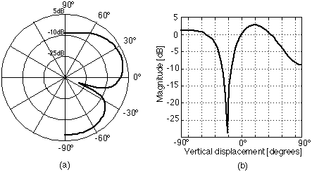
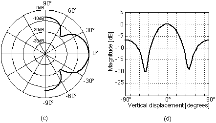
where wn is the normalized frequency (w / wc), wc is the crossover frequency, Ms is the magnitude frequency response of the system, and T*n is the normalized time delay between low and high-frequency drivers. The normalized lobing error gives the designer an indication of how a system will change in its performance when the listener is incrementally off-axis. It does not, however, provide a comprehensive figure-of-merit for the off-axis behavior of the system over significant vertical displacements. All noncoincident (2,2) systems exhibit radiation lobes in the vertical plane around the crossover frequency. Polar axis tilt refers to the amount by which the primary lobe of a loudspeaker system at the crossover frequency diverges from the design axis [1], [3]. Fig. 2 gives some examples of the lobing behavior for two common crossover networks. The system of Figs. 2(a) and 2(b) has approximately 20 degrees of polar axis tilt while the system of Figs. 2(c) and 2(d) is free of polar axis tilt.
Fig. 2. Typical lobing behavior at the crossover frequency for (2,2) configurations. Third-order Butterworth network, high-frequency driver connected with positive polarity -- (a) polar and (b) Cartesian views. Fourth-order Linkwitz-Riley network -- (c) polar and (d) Cartesian views. It is widely felt that the optimum radiation pattern for noncoincident systems is one where the polar axis tilt is zero [2], [3]. It is felt that such a behavior minimizes coloration in the loudspeaker's reverberant response [2]. We can see from Fig. 2(c) (and also by definition) that when a system is free of polar axis tilt, the system response will have a maximum on the design axis. Since the normalized lobing error is the derivative of the magnitude response of the system with respect to vertical displacement evaluated when the vertical displacement is zero, the normalized lobing error will be zero if the system has a maximum (or minimum) when the vertical displacement is zero, that is, along the design axis. Thus, the normalized lobing error can be used to determine whether a system is free of polar axis tilt. (Analysis of additional derivatives or other means can then be used to confirm whether the zero corresponds to a maximum or minimum.) Analysis has shown that for (2,2) systems the primary radiation lobe at the crossover frequency will be on the design axis only if the interdriver phase difference is zero [1], [2].
Previous work has demonstrated that (3,2) systems have zero lobing error and are free of polar axis tilt independent of interdriver phase relationships [3]. The work rigorously proves what might seem intuitively obvious given our understanding of polar axis tilt and normalized lobing error. (It might certainly be expected that a vertically symmetric array has vertically symmetric radiation and hence is free of polar axis tilt -- and by direct consequence has zero lobing error.) In addition, the behavior of the primary lobe of (3,2) systems has been analyzed in [3] to determine the interdriver phase relationships required to maximize the smoothness of the vertical radiation in the vicinity of the crossover frequency. The analysis demonstrates that when the low and high-frequency drivers are in phase quadrature, the vertical radiation at the crossover frequency will be the widest possible and that when the interdriver phase shift is zero, a fairly narrow lobe will result. We are thus left with a good analysis of how (3,2) systems behave in the vicinity of the crossover frequency. One might say that the prior work has left us a good understanding concerning the first two of the three interdriver interactions mentioned above, but only a limited understanding of the third. 2.1 Discussion Both the concepts of normalized lobing error and polar axis tilt were developed to aid in the design and analysis of particular aspects of binary loudspeaker systems -- that is, systems which involve the interaction of only two sub-systems, and which, by necessity, interact only over the limited range of frequencies around the crossover point. As such, they represent robust tools for the analysis of (2,2) systems. A (3,2) system, however, is trinary in nature, involving the three interdriver interactions already mentioned. One might thus question the applicability of tools developed for binary, (2,2) systems to the trinary, (3,2) regime. For example, normalized lobing error predicts the behavior of systems only for incremental deviation from the design axis. However, it is inconceivable that the multplicity of driver interactions inherent in the (3,2) arrangement results in significant lobing mechanisms which manifest themselves only nonincrementally off axis. As another example, polar axis tilt concerns itself with the radiation behavior only at the crossover frequency. However, there is driver interaction in the (3,2) arrangement which occurs well away from the crossover frequency between the two low-frequency drivers. One might suspect that this interaction can contribute to significant lobing behvior. If it does, it will be completely missed by a conventional analysis based on polar axis tilt.
One source of off-axis coloration in (3,2) systems that escapes both a normalized lobing error analysis as well as a polar axis tilt analysis is due to destructive interference between the two low-frequency drivers. In a (3,2) system, the two low-frequency drivers are identical and are driven with identical electrical signals. Thus, along the design axis, the interdriver phase shift between the low-frequency drivers is zero at all frequencies. However, as the vertical displacement is increased or decreased, one driver's output will be advanced in time, while the other will be retarded. This introduced time displacement will result in interference effects in the summed response of the two low-frequency drivers. Indeed, at small vertical displacements, it is this very phenomenon that gives (3,2) systems their unique polar behavior around the crossover frequency. However, at frequencies where the time displacement between the two low frequency drivers corresponds to one-half of one wavelength, the outputs of the two low frequency drivers will null. The relationship between the lowest frequency null in the summed low-frequency driver response and the vertical angular displacement is:
where fx is the lowest frequency of total cancellation in Hz, [theta] is the vertical displacement (ranging from -90 deg. to +90 deg.), d is the vertical separation between the high-frequency driver and one low-frequency driver, L is the distance from the plane of the drivers to the on-axis design point, and c is the velocity of sound. For a given d, as [theta] increases in magnitude, fx decreases. Clearly, if d and [theta] are sufficiently large, it is possible that fx will occur at a frequency where the output from the high-frequency driver is negligible, and the system response at that frequency at that listening angle will effectively drop to zero. As a typical example, we will consider a (3,2) system employing two 110 mm low-frequency drivers with frame diameters of 130 mm and a conventional 25 mm high-frequency driver with a 104 mm facia. In this case, the minimum physically possible d will be 117 mm. Typically, the crossover frequency will be around 2 kHz. Using the above figures and setting L at 2.0 m and [theta] to 45 deg., Eqn. (2) gives a resulting fx of 1.043 kHz. With a third-order Butterworth crossover, the high-frequency driver output will be 17 dB down at 1.043 kHz. Clearly, fx is in a range where the tweeter will be contributing negligibly to the system output. (The figure chosen for [theta] is arguably the minimum vertical displacement over which a loudspeaker system response must be smooth to prevent perceptible colorations in the reverberant response in a typical listening environment.) This analysis suggests an additional constraint on the design of (3,2) systems is needed. Specifically, if significant off-axis nulls are to be avoided, (3,2) systems must be designed such that the lowest frequency null in the low-frequency drivers' summed response is masked by the output from the high-frequency driver for all vertical displacements of significance, which is to say: fx must fall at a frequency where the output from the tweeter is still significant. This new constraint can be strictly satisfied if we impose a new design objective: that fx at the maximum vertical displacement be made greater than or equal to fc, the system crossover frequency. Eqn. (2) can then be employed to determine the maximum d that will satisfy the above objective. Returning to the prior example of a (3,2) system, for fx >= fc = 2.0 kHz, L = 2.0 m, and [theta] = 45 deg., the maximum d allowed by Eqn. (2) is 61 mm. Thus it is physically impossible to meet the new objective with the given low-frequency drivers. However, it is possible to meet the objective if smaller diameter drivers are used. If a 25 mm high-frequency driver with a compact magnetic structure is employed along with a custom molded cabinet baffle, a 30 mm effective facia may be possible. This leaves 92 mm available for the low-frequency driver frame diameter. While it is not possible to strictly meet the new objective using 110 mm drivers, improvements in vertical radiation will nonetheless result if the interdriver spacing is reduced. For example, if the same 110 mm low-frequency drivers from the above example are used in conjunction with a commercially available 28 mm high-frequency driver employing a compact neodymium magnet system and having a 54 mm facia, the interdriver spacing can be reduced to 92 mm. The resulting fx at [theta] = 45 deg. is now 1.327 kHz. Again assuming a third-order Butterworth crossover at 2.0 kHz, the high-frequency driver's output will be 11 dB down at 1.327 kHz, an improvement of 6 dB over the case where d is 117 mm. Thus the original constraint -- that there be significant output from the high-frequency driver at fx -- is marginally satisfied.
To verify the above findings, as well as to determine whether there are other phenomena which might significantly affect the off-axis behavior of (3,2) systems, a model of the radiation from a (3,2) system was implemented in a high level mathematical programming language. High frequency drivers were modeled as point sources while low frequency drivers were modeled as flat pistons [4] to account, albeit crudely, for driver directivity. (The approach used is similar to the one used by Vanderkooy [5] in an unrelated study.) Using the model, plots of the magnitude of the frequency response at several vertical displacements were generated for several (3,2) systems over the audio frequency range. The systems examined are characterized as follows:
For comparison purposes, two conventional (2,2) systems were also examined:
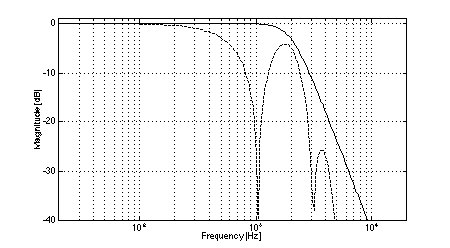
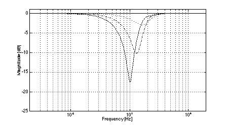
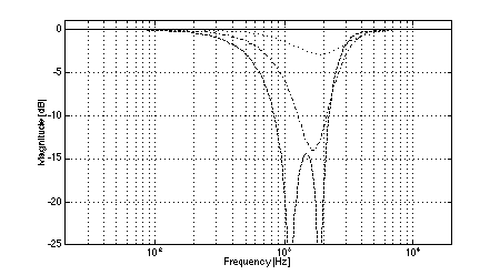
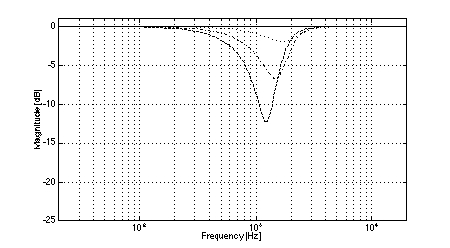
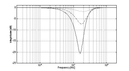
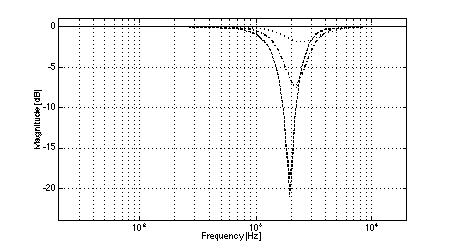
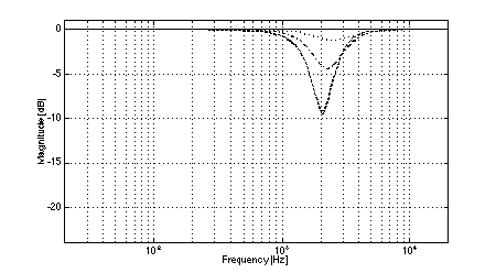
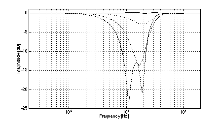
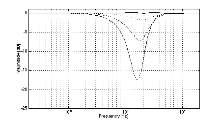
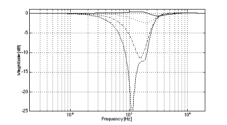
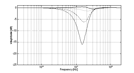
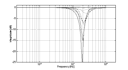
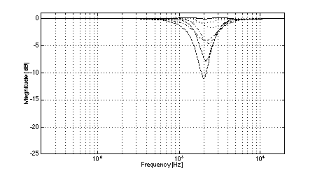
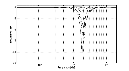
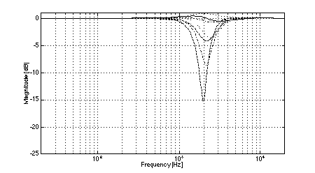
In all cases, the crossover frequency was 2.0 kHz, L was 2.0 m, and the diameters of the low-frequency pistons were set to 100 mm (to most closely model the behavior of a typical loudspeaker cone of 110 mm diameter). The simulations clearly show the effects of low-frequency off-axis destructive interference in (3,2) systems. Fig. 3 shows the expected comb-filter-like response of two time-displaced lowpass functions, with nulls occurring at 1.04 kHz and higher multiples. As predicted, in the cases where the separation between low frequency drivers is large (i.e., systems 1 and 2, Figs. 4 and 5), the resulting nulls in the system response are quite severe at large vertical displacements. At the maximum vertical displacement of 45 deg., system 1 exhibits a 17.5 dB null at the predicted fx of 1.04 kHz while system 2 nulls to greater than 35 dB. (Small differences between the results of the simulations and the theoretical predictions are attributed to the finite frequency resolution of the simulations and to the effects of driver directivity which were included in the simulations but not in the analysis above.) The superior performance of system 1 in the region where the low-frequency driver null as compared to system 2 is attributable to the fact that the high-frequency driver in system 1 rolls off at a lower rate than is the case in system 2. In addition to the null caused by low-frequency driver interference, System 2 exhibits another off-axis null just below the crossover frequency. In the cases where the separation between low-frequency drivers is small (i.e., systems 3 and 4, Figs. 6 and 7), the cancellation due to destructive interference is much reduced and occurs at a slightly higher frequency. In the case of system 3, a 12.5 dB notch is observed at the predicted fx of 1.3 kHz. System 4 is also 12.5 dB down at fx. However, owing to the phase relationships between the low and high-frequency drivers, a maximum system cancellation of 21 dB occurs near 1.6 kHz. In any event, the improvement in off-axis performance is still appreciable as compared to system 2. Both (2,2) systems used for reference exhibit the expected single off-axis cancellation at the crossover frequency. System 5 (with larger interdriver spacing, Fig. 8) exhibits a maximum 21 dB notch near fc (at the maximum vertical displacement), while system 6 (with small interdriver spacing, Fig. 9) has a maximum dip of 9 dB (again at the maximum vertical displacement). Comparing the best of the (3,2) systems to the best of the (2,2) systems, we observe that system 4 has a 12.5 dB dip at 1.3 kHz, and system 6 has a 9 dB dip at 2.0 kHz, i.e., the (2,2) system's notch 3.5 dB less severe. This suggests that the elimination of lobing error and polar axis tilt independent of interdriver phase relationships may not be sufficient reasons to utilize a (3,2) arrangement over a (2,2) arrangement using similar drivers.
Fig. 3. Magnitude response of system 1, low-frequency drivers only: on-axis (solid), +/-45 deg. vertical displacement (dashed).
Fig. 4. Magnitude response of system 1: on-axis (solid), +/-15 deg. vertical displacement (dotted), +/-30 deg.vertical displacement (dash-dot), +/-45 deg.vertical displacement (dashed).
Fig. 5. Magnitude response of system 2: on-axis (solid), +/-15 deg. vertical displacement (dotted), +/-30 deg.vertical displacement (dash-dot), +/-45 deg.vertical displacement (dashed).
Fig. 6. Magnitude response of system 3: on-axis (solid), +/-15 deg. vertical displacement (dotted), +/-30 deg.vertical displacement (dash-dot), +/-45 deg.vertical displacement (dashed).
Fig. 7. Magnitude response of system 4: on-axis (solid), +/-15 deg. vertical displacement (dotted), +/-30 deg.vertical displacement (dash-dot), +/-45 deg.vertical displacement (dashed).
Fig. 8. Magnitude response of system 5: on-axis (solid), +/-15 deg. vertical displacement (dotted), +/-30 deg.vertical displacement (dash-dot), +/-45 deg.vertical displacement (dashed).
Fig. 9. Magnitude response of system 6: on-axis (solid), +/-15 deg. vertical displacement (dotted), +/-30 deg.vertical displacement (dash-dot), +/-45 deg.vertical displacement (dashed).
In this paper, we have demonstrated that there is at least one significant source of off-axis response error present in (3,2) systems that is not predictable by conventional normalized lobing error or by polar axis tilt analyses. This error, caused by destructive interference between the two low-frequency drivers, has been shown to manifest itself in typical (3,2) implementations. We have suggested a new constraint to minimize the influence of low-frequency interdriver interference on the off-axis response and have presented an analytical relation to assist in designing systems which satisfy the constraint. We have shown through analysis and comprehensive computer simulations that it is possible to build systems using newly available high-frequency drivers with compact magnetic structures which satisfy the new constraint. Even so, simulations demonstrate that for such systems, the off-axis behavior can be worse than that of a (2,2) system employing the same drivers. This suggests that the decision to utilize a (3,2) arrangement must be made over and above the consideration that (3,2) systems are free of lobing error and polar axis tilt. One cited advantage of (3,2) systems is that they have double the maximum volume displacement at low frequencies over (2,2) systems employing identical drivers [6]. However, other arrangements employing two similar low-frequency drivers and one high-frequency driver are possible, and it is likely that some of these will effectively yield the off-axis behavior of (2,2) systems while retaining the power handling benefits of a (3,2) arrangement. These possibilities cannot be dismissed without consideration.
[1] S. H. Linkwitz, "Active Crossover Networks for Noncoincident Drivers," J. Audio Eng. Soc., vol. 24, pp. 2-8 (1976 Jan./Feb.). [2] S. P. Lipshitz and J. Vanderkooy, "A Family of Linear-Phase Crossover Networks of High Slope Derived by Time Delay," J. Audio Eng. Soc., vol. 31, pp. 2-20 (1983 Jan./Feb.). [3] J. A. D'Appolito, "A Geometric Approach to Eliminating Lobing Error in Multiway Loudspeakers," AES Preprint 2000, presented at the 74th Convention of the Audio Engineering Society, October, 1983. [4] L. E. Kinsler, A. R. Frey, A. B. Coppens, and J. V. Sanders, Fundamentals of Acoustics Third Edition (John Wiley & Sons, New York, 1982), pp. 176-182. [5] J. Vanderkooy, "A Simple Theory of Cabinet Edge Diffraction," J. Audio Eng. Soc., vol. 39, pp. 923-933 (1991 Dec.). [6] J. A. D'Appolito, "A High-Power Satellite Speaker," Speaker Builder, vol. 5, pp. 7-14 (4/84).
ADDITIONAL SYSTEM SIMULATIONS The results of eight additional system simulations are presented here. These systems were not discussed in the main text as they contribute little additional insight into the concepts developed there. However, insofar as they represent the behavior of "real-world" systems, their inclusion was considered to be of some value. The systems included in this appendix employ transfer functions that are typical for systems in which all drivers are mounted on a common, flat baffle (i.e., systems in which the low-frequency drivers are retarded in time with respect to the high-frequency driver). Specifications for the systems appear in Table AI and the results of the simulations appear in Figs. A1-A8.
In the above table, d is the vertical interdriver spacing (in millimeters), HL is the lowpass transfer function, HH is the highpass transfer function, and a is the crossover spreading factor (wnL = 2*pi*fc/a and wnH = 2*pi*fc*a). In all cases, the low-frequency drivers are 25 mm behind the high-frequency driver, the diameters of the low-frequency pistons are 100 mm, fc = 2.0 kHz, and L = 2.0 m. The (3,2) suffix indicates systems of (3,2) configuration; the (2,2) suffix indicates systems of (2,2) configuration.
Fig. A1. Magnitude response of system lp3hp3f(3,2): on-axis (solid), +/-15 deg. vertical displacement (dotted), +/-30 deg.vertical displacement (dash-dot), +/-45 deg.vertical displacement (dashed).
Fig. A2. Magnitude response of system lp3hp3fs(3,2): on-axis (solid), +/-15 deg. vertical displacement (dotted), +/-30 deg.vertical displacement (dash-dot), +/-45 deg.vertical displacement (dashed).
Fig. A3. Magnitude response of system lp4hp4f(3,2): on-axis (solid), +/-15 deg. vertical displacement (dotted), +/-30 deg.vertical displacement (dash-dot), +/-45 deg.vertical displacement (dashed).
Fig. A4. Magnitude response of system lp4hp4fs(3,2): on-axis (solid), +/-15 deg. vertical displacement (dotted), +/-30 deg.vertical displacement (dash-dot), +/-45 deg.vertical displacement (dashed).
Fig. A5. Magnitude response of system lp3hp3f(2,2): on-axis (solid), +/-15 deg. vertical displacement (dotted), +/-30 deg.vertical displacement (dash-dot), +/-45 deg.vertical displacement (dashed).
Fig. A6. Magnitude response of system lp3hp3fs(2,2): on-axis (solid), +/-15 deg. vertical displacement (dotted), +/-30 deg.vertical displacement (dash-dot), +/-45 deg.vertical displacement (dashed).
Fig. A7. Magnitude response of system lp4hp4f(2,2): on-axis (solid), +/-15 deg. vertical displacement (dotted), +/-30 deg.vertical displacement (dash-dot), +/-45 deg.vertical displacement (dashed).
Fig. A8. Magnitude response of system lp4hp4fs(2,2): on-axis (solid), +/-15 deg. vertical displacement (dotted), +/-30 deg.vertical displacement (dash-dot), +/-45 deg.vertical displacement (dashed).
copyright © 1995 Mithat Konar
-- all rights reserved. |
|||||||||||||||||||||||||||||||||||||||||||||||||||
|
|
|||||||||||||||||||||||||||||||||||||||||||||||||||
|
Site copyright ©2005 Biro Technology–all rights reserved
|
|||||||||||||||||||||||||||||||||||||||||||||||||||
